Connecting an External Sensor to an MPVI Pro
The analog inputs on the MPVI Pro's Enhanced IO connector can be used to attach up to four devices (such as many types of wideband sensor) that generate an analog output.
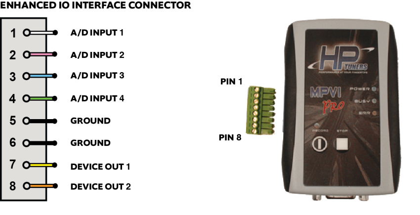
Enhanced I/O Connector Analog Inputs
The EIO connector provides the following for connecting analog inputs:
|
■
|
Four high impedance, buffered, filtered, 10 bit 0-5v analog to digital conversion channels that can connect to almost any device.
Input impedance greater than 4 meg ohm. A/D inputs can tolerate short term over voltage without damage. |
|
■
|
Two ground reference tie points. |
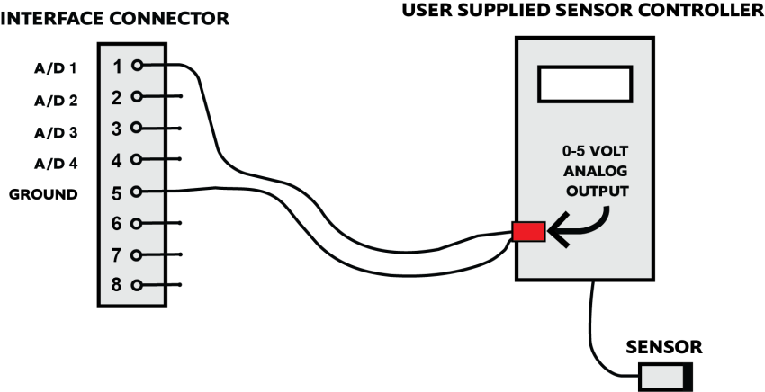
The following circuit shows the connection between the 0-5 volt analog output from an aftermarket wide band controller or EGT sensor (Exhaust Gas Temperature) using the supplied pigtail connector.
Refer to the manufacturer’s documentation for additional information on connecting and configuring their device.
Connecting an Analog Input
|
1.
|
Connect the analog signal from the external sensor to one of the four A/D inputs on the EIO connector. |
|
2.
|
Connect the ground from the sensor output to the ground on the EIO connector. |
|
3.
|
Ensure that your EIO connector is properly attached to your MPVI interface device. |
|
4.
|
Connect the interface device to a USB port on your computer and to the OBD-II port on the vehicle. |
|
5.
|
Open VCM Scanner and connect to the vehicle. |
|
6.
|
If the Channels list is not already open, click the tab on the left edge of the screen to display it. |
|
8.
|
Go to External Inputs > MPVI Pro and then double-click on the A/D input that you connected the sensor to in Step 1. |
|
9.
|
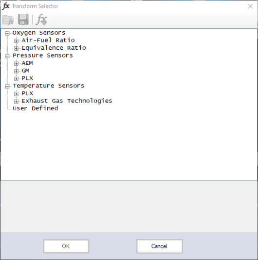
The selected input should now appear in the Channels list. Right-click on it and select Transform. The Transform Selector window appears. This window specifies how the raw voltages received through the EIO connector must be transformed into usable sensor data. |
|
10.
|
Browse for the sensor you connected in Step 1. If the sensor appears in the list, select it and click OK. |
If the sensor does not appear in the list or you need to customize a transform to account for a signal/noise offset, you can define the appropriate transform manually. See Defining Your Own Transform to complete channel setup.
Channel setup is now complete. It can now be added to gauges, graphs, charts, etc. just like any other channel. When selecting the parameter to include, use the transform you chose in Step 10.

 icon in the Channels list. The Channel Selector window appears.