
Messages from a 500 kbps CAN bus can be added to the data stream received by MPVI2 (via Pro Link) and MPVI2+/3 (via Pro Link+).
NOTE: In order to use this feature, you must have a Pro Feature Set license for the interface device you are using the Pro Link / Pro Link+ with.
Pro Link Pinouts
|
Wire Color |
Description |
|---|---|
|
Black |
GND |
|
Red |
Analog 1: 0 - 5 V, 100 Hz Sampling Rate |
|
Blue |
Analog 2: 0 - 5 V, 100 Hz Sampling Rate |
|
Orange |
CAN High |
|
Yellow |
CAN Low |
Adding a CAN Bus Input
| 1. | Connect the "high" output from the CAN bus to the ORANGE wire on the Pro Link cable. |
| 2. | Connect the "low" output from the CAN bus to the YELLOW wire on the Pro Link cable. |
| 3. | Ensure that your Pro Link Cable is properly attached to your MPVI2 (or later) interface device. |
| 4. | Connect the interface device to a USB port on your computer and to the OBD-II port on the vehicle. |
| 5. | Open VCM Scanner and connect to the vehicle. |
| 6. | If the Channels list is not already open, click the tab on the left edge of the screen to display it. |
| 7. | Click the  icon in the Channels list. The Channel Selector window appears. icon in the Channels list. The Channel Selector window appears. |
| 8. | All of the folders after the Serial Port folder in External Inputs contain CAN bus inputs (listed by manufacturer). Double-click on the sensor that you want to add. |
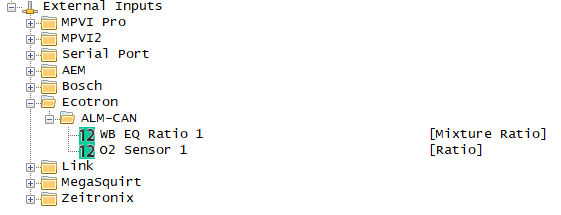
NOTE: If the sensor you wish to add is not listed, Contact HP Tuners Support to request that it be added.
The selected input should now appear in the Channels list.
